
Ge VAT20 vfd
Hi everybody,
The VAT20 is a micro AC variable speed drive that can be used to control the speed of three-phase induction AC motors ranging from 0.2 to 2.2kW. It features a built-in keypad and display for easy operation, and has a protection degree of either IP20 or IP65. It also has a built-in EMC filter for use in industrial environments, and is DIN rail mountable with the use of an optional kit. Additionally, it meets global standards such as CE and cUL.
* This VFD is designed to be a reliable and versatile solution for controlling the speed of induction motors in a variety of industrial and commercial applications.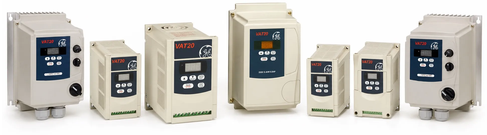
The control system for the sinusoidal wave PWM inverter features an output frequency range of 0 to 200Hz, with voltage/frequency constant torque, constant power, and torque boost. There are six selectable pre-set patterns, and the overload capacity is 150% for 60 seconds. The carrier frequency is selectable between 4 to 16kHz, with a frequency setting resolution of 0.1Hz (0-99.9Hz) for digital, and 0.1Hz/60Hz for analog. The acceleration/deceleration can be set between 0.1 and 999 seconds, and can be set individually.
The operating system has two mode selections: forward run by the FWD input, reverse run by the REV input, or run by the FWD input with forward/reverse command by the REV input. The stopping system is selectable between ramp down or coast to stop. The DC braking feature has a starting frequency of 1-10Hz, and a level of 0-20% with a braking time of 0-25.5 seconds. The frequency limit has an upper limit of 1-200Hz and a lower limit of 0-200Hz.
Other functions include auto re-start, auto reset, flying start, and jog slow speeds. These functions provide additional versatility and flexibility for the control system, making it suitable for a wide range of applications.
About the protection features and I/O configuration of the sinusoidal wave PWM inverter.
The protection features of the inverter include prevention measures such as overcurrent limitation, overvoltage limitation, and stall prevention, as well as trip protection for conditions such as overload, overvoltage, undervoltage, overcurrent, power loss, output short-circuit, grounding fault, and overtemperature. The last three faults are recorded in the fault history.
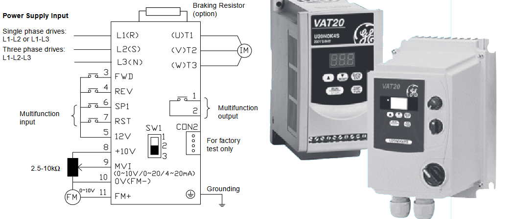
The I/O configuration of the inverter includes a 3-digit, 7-segment display with 5 operation keys for the operation panel. There are four digital inputs (2 of which are programmable) for sequence input, and one programmable relay output for sequence output. The frequency setting input is one analogue input that can be configured as 0-10V, 4-20mA, or 0-20mA. There is a 10 VDC source for a 2-10kΩ potentiometer, and 0-10 VDC analogue outputs for frequency output display.
The inverter is designed for indoor installation in an atmosphere free from corrosive or explosive gases, dust, steam, or oil mist. The protection degree is either IP20 or IP65. The temperature range for the inverter is from -10 to 50°C, with a relative humidity of 0-95% without condensation. The inverter is also designed to withstand vibrations under 1G (9.8 m/s2). The inverter meets global standards such as cUL and CE.
The digital inputs of the inverter include the FWD (Forward run) input, REV (Reverse run) input, SP1 (Multifunction input), and RST (Fault reset) input. The SP1 input is programmable and can be used for functions such as jog, slow speed, emergency stop, output shut off, or reset, while the RST input is programmable and set to reset function as default, but can also be used for jog, slow speed, emergency, or output shut off.
The digital outputs of the inverter include the Trip relay (Multifunction output) which is programmable and set to fault function as default, but can also be used for run status and frequency reached.
The analogue inputs of the inverter include the MVI (Frequency setting) input, which is programmable and can accept a frequency signal input of 0-10V, 4-20mA, or 0-20mA. There is also a common analogue I/O (0V) for all analogue inputs.
The analogue outputs of the inverter include the FM (Frequency output) which is an analogue output of 0-10V and can be used as a speed meter. There is also a common analogue I/O (0V) for all analogue outputs. Additionally, the inverter includes a 10V DC source (10V DC power supply) for a 2-10kΩ potentiometer (2W).
++ Ge VAT20 VFD User Manual (pdf)
++ Ge VAT20 VFD Quick start (pdf)
----------
+ General Electric 2. Main page >
+ VFD Homepage >
 -