
Electrical Measurement and Test Concepts
Electrical Measurement and Test Concepts
Electrical measurement determines the value of a quantity such as voltage, current or resistance. Electrical testing investigates whether a circuit, device or protective measure meets specified requirements. A motor that runs is not necessarily electrically safe. This guide explains the main concepts and connects them to the relevant specialist topics.
What do voltage, current, resistance and power mean?
Voltage (V) is the electrical potential difference between two points; current (A) describes the flow of charge, and resistance (Ω) describes opposition to that flow. For an ohmic element, V = I × R applies. Active power (W) and energy (Wh or kWh) are different: power describes the rate of energy consumption, while energy describes consumption over time. In AC systems, multiplying voltage by current does not always give active power; power factor and waveform also matter. See power metering and monitoring devices.
How do you choose a measuring instrument?
A multimeter measures voltage, resistance and other quantities depending on its capabilities. A clamp meter must suit the current range and AC/DC requirement. For load current, the clamp normally surrounds one conductor. Clamping around line and neutral together largely cancels their magnetic effects. For leakage current measurement, the relevant live conductors are enclosed together to investigate residual current; the arrangement depends on the system.
Test probes and leads are part of the measuring system. Damaged insulation, the wrong input socket or unsuitable accessories can affect both safety and results. Test and measuring circuit safety cannot be assessed from the maximum voltage printed on the meter alone.
Resolution, accuracy and uncertainty
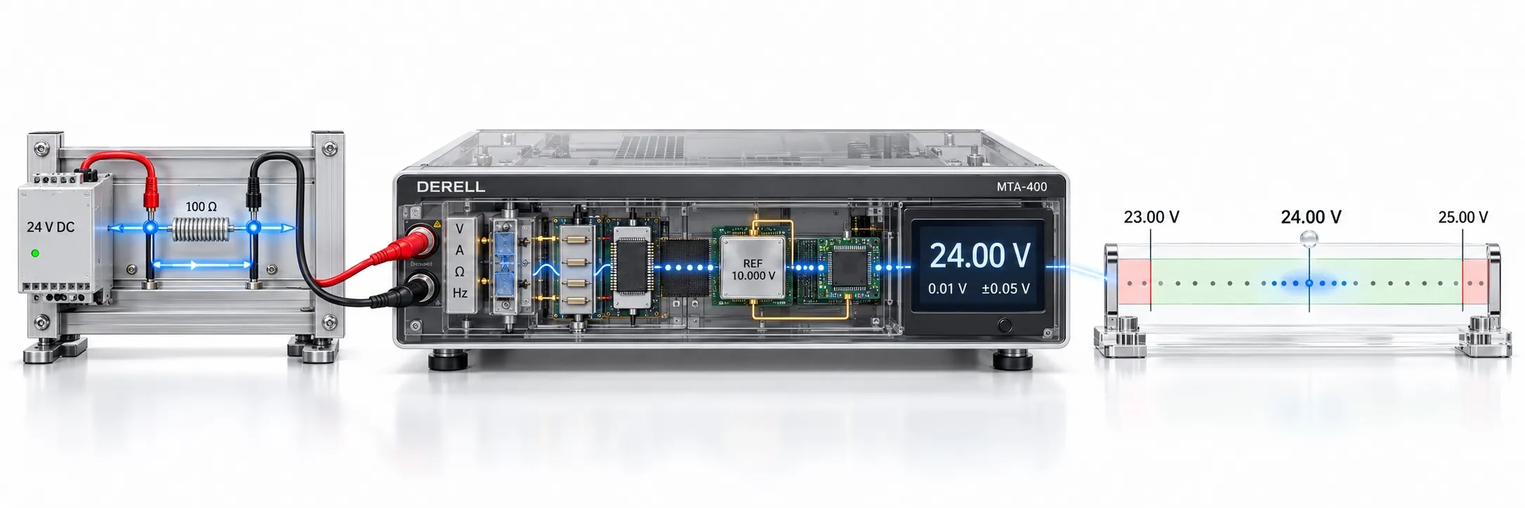
Resolution concerns the small changes a display can distinguish. Accuracy concerns agreement with the true value; repeatability concerns agreement between results under the same conditions. More display digits do not automatically mean greater accuracy. Measurement uncertainty describes the dispersion of values that can be attributed to the quantity being measured; the instrument, connections, environment and method can contribute. Calibration establishes relationships with references; it is distinct from adjustment or repair.
Example: Suppose an instrument has a specified error limit of ±(0.5% of reading + 2 digits), reads 24.00 V and has a least significant digit of 0.01 V on the selected range. The calculation is ±(0.12 + 0.02) = ±0.14 V. Here, one digit means one step of the last display digit. This calculates a manufacturer's limit under specified conditions; it is not a complete measurement uncertainty budget.
AC, DC and True RMS
Select the correct function for DC or AC. True RMS is useful for measuring the effective value of non-sinusoidal AC signals, within the instrument's bandwidth, crest factor and operating limits. A True RMS label alone does not establish suitability for a drive's PWM output; use a function and procedure intended for drive measurements. Power quality instruments provide a different type of investigation into waveform-related problems.
Are continuity, insulation and earthing the same test?
A continuity test checks for a conducting path. A multimeter beep does not establish that a connection will perform properly under load or that insulation is sound. Protective conductor and bonding resistance must be evaluated using the appropriate test current and method. Insulation resistance examines insulation under a specified test voltage. Resistance to earth and earth fault loop impedance are different quantities and cannot be substituted for each other.
Before insulation testing, de-energize the circuit and verify absence of voltage. Isolate PLCs, HMIs and other electronic equipment, including drives, from the test voltage as required by their manufacturers. Select the test voltage and acceptance limit for the equipment and applicable standard. Insulation and hipot test safety also includes checking that stored charge has been safely discharged after testing.
What do protective and monitoring devices check?
An RCD tester examines residual current protection's tripping behaviour under suitable conditions; the device's test button does not replace installation verification. A residual current monitor (RCM) monitors current; any automatic disconnection function requires separate evaluation. In IT systems, an insulation monitoring device (IMD) monitors insulation condition, while an insulation fault location system (IFLS) helps locate a fault. A phase sequence tester checks the order of the three phases.
CAT ratings and absence of voltage
CAT II, CAT III and CAT IV relate to transient overvoltage conditions at the measurement location. Read the category and voltage rating together; CAT III 600 V does not authorize use at 600 V in every environment. The instrument, probes and accessories must all suit the location. A non-contact AC voltage indicator is useful for preliminary checks; it does not by itself prove absence of voltage.
Before de-energized work, isolate the supplies, prevent re-energization and verify absence of voltage between the relevant conductors using a suitable contact instrument. Check the instrument against an appropriate proving source before and after the verification. Account separately for stored energy and additional supplies, including capacitors, UPS systems and solar installations. Energized tests require competent personnel, an appropriate work procedure and protective equipment.
How should results be recorded and assessed?
A test record should include the measurement location, instrument and calibration details, range, test conditions, result and acceptance criterion. There is no single resistance or leakage current limit valid for all equipment. Select multifunction installation testers and machinery electrical safety testers for the application. IEC 60364-6 addresses installation verification, while the IEC 61557 series addresses equipment for testing, measuring or monitoring protective measures.
Technical sources: BIPM — VIM · Fluke — Accuracy & resolution · Fluke — True RMS · IEC 61557-1