
What is the difference between RS-232 RS-422 and RS-485?
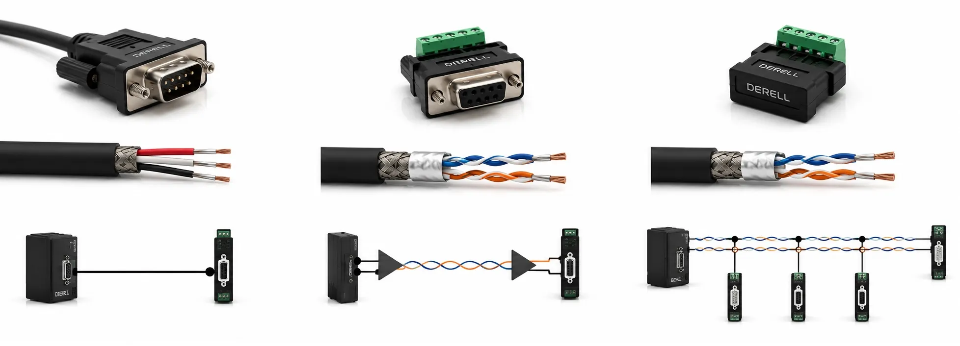
RS-232, RS-422 and RS-485 are electrical interface standards used to carry serial data between devices. Their main differences are not simply speed or cable length. They differ in single-ended versus differential signalling, network topology, number of drivers and receivers, noise immunity and practical distance-versus-data-rate capability.
In simple terms: RS-232 is mainly used for a short point-to-point connection between two devices. RS-422 uses differential signalling and is better suited to longer distances and electrically noisy environments, but normally uses one driver on a signal pair. RS-485 also uses differential signalling and allows multiple devices to share the same bus, which is why it is extremely common in industrial automation.
What is RS-232?
RS-232 is a single-ended serial electrical interface. The receiver interprets the signal voltage relative to a common reference conductor rather than comparing two complementary signal wires.
A simple RS-232 connection may use TX, RX and signal ground, but RS-232 is not limited to only two signal lines. Traditional implementations can also include RTS, CTS, DTR, DSR and other hardware flow-control or modem-control signals.
RS-232 is mainly intended for point-to-point communication. It can still be found on older PLC programming ports, laboratory instruments, modems, serial peripherals and some industrial controllers or HMI panels.
Because RS-232 uses single-ended signalling, it is generally more sensitive to ground-potential differences and electromagnetic interference than differential RS-422 or RS-485 links. For this reason, it is normally associated with shorter cable runs.
What is RS-422?
RS-422 uses balanced differential signalling. The receiver determines the data state from the voltage difference between two conductors rather than measuring one signal conductor against ground.
When electrical noise couples similarly into both conductors, much of that common-mode interference can be rejected by the differential receiver. This gives RS-422 a significant advantage over RS-232 for long cables and electrically noisy installations.
A conventional RS-422 network supports one driver communicating with multiple receivers. Classic RS-422 loading allows one driver to serve up to ten standard receiver loads. This is an important distinction from RS-485, which is specifically designed to allow multiple drivers to share a multipoint bus.
For full-duplex communication between two devices, separate differential pairs can be used for transmit and receive. One pair carries data in one direction while the second pair carries data in the opposite direction.
RS-422 signalling is also common outside conventional command/response serial networks. Some high-speed incremental encoders, for example, provide differential A/A−, B/B− and Z/Z− line-driver outputs based on RS-422 electrical principles.
What is RS-485?
RS-485 also uses differential signalling, but it was developed specifically for multipoint bus networks. Multiple device drivers can be connected to the same communication bus and take turns driving the line according to the rules of the higher-level communication protocol.
The most common industrial arrangement is two-wire half-duplex RS-485. The same differential pair is used for both transmission and reception. When one device is transmitting, the other devices release the bus and listen.
RS-485 can also be implemented as a four-wire system with separate transmit and receive pairs. It is therefore inaccurate to say that RS-485 itself is always half-duplex.
Traditional RS-485 loading is specified in terms of 32 unit loads, not an absolute modern limit of 32 physical devices. Current transceivers may present 1/2, 1/4 or 1/8 of a traditional unit load, allowing appropriately designed networks to contain considerably more than 32 nodes.
RS-485 is widely used with Modbus over RS-485, PLC networks, motor drives, energy meters, temperature controllers and distributed I/O systems.
What is the main difference between RS-422 and RS-485?
RS-422 and RS-485 are often confused because both use differential electrical signalling. The main difference is not that “RS-485 is faster” or “RS-485 always reaches farther.”
RS-422 is primarily a one-driver, multiple-receiver system. RS-485 allows multiple drivers on the same multipoint bus. An RS-485 transmitter can enter a high-impedance state when it is not using the network, allowing another station to drive the same pair.
This makes RS-485 particularly suitable for networks where one controller needs to communicate with many devices over a common cable. A PLC can, for example, poll several drives or instruments connected to the same RS-485 bus using a protocol such as Modbus RTU.
Which standard supports the longest distance?
RS-422 and RS-485 generally support much longer cable runs than RS-232 because of their differential signalling. At relatively low data rates and with suitable cable, installations in the approximately 1200-metre class are possible.
That figure should not be treated as a universal guaranteed distance. Maximum practical cable length decreases as the data rate increases. Cable impedance and capacitance, termination, network topology, transceiver characteristics and electromagnetic conditions all influence real performance.
A design should therefore follow the specifications of the actual devices and cable rather than relying on a statement such as “RS-485 always works at 1200 metres.”
Which interface has better noise immunity?
In general, RS-422 and RS-485 provide better noise immunity than RS-232 because they use differential signalling. Noise that appears similarly on both conductors can largely cancel when the receiver evaluates the voltage difference.
This is one reason differential serial interfaces are common around contactors, motors, servo amplifiers and variable frequency drives. However, differential signalling does not make poor installation practices harmless. Cable routing, shielding, grounding and common-mode voltage limits still matter.
Where is termination required?
On long or high-speed differential links, termination is used to reduce signal reflections by matching the electrical characteristics of the cable.
For a conventional RS-422 link, termination is normally placed at the receiving end of the transmission line. In a two-wire multipoint RS-485 bus, termination is typically installed at the two physical ends of the main bus.
Installing termination at every RS-485 device can overload the network. Some RS-485 systems may also require bias or fail-safe resistors to establish a defined bus state while no transmitter is actively driving the line.
Are RS-232, RS-422 and RS-485 communication protocols?
They should not be treated as application protocols in the same sense as Modbus. RS-232, RS-422 and RS-485 primarily define electrical interface and physical-layer characteristics. They do not by themselves define the meaning of registers, commands or application data.
For example, Modbus defines function codes, data addresses and message behaviour. A Modbus RTU message may then be transported electrically over an RS-485 network.
Similarly, an encoder can use an RS-422-compatible differential electrical output without using Modbus or any register-based industrial communication protocol.
What is UART?
UART — Universal Asynchronous Receiver/Transmitter is not an RS-232- or RS-485-style electrical interface standard, and it is more accurate to describe it as a hardware peripheral or communication block than as a complete communication protocol.
A UART converts data into an asynchronous serial bit stream for transmission and converts received serial bits back into data for the processor. A typical UART frame can contain a start bit, data bits, optional parity and one or more stop bits.
The communicating devices must agree on parameters such as baud rate, number of data bits, parity and stop bits.
The TX and RX pins on a microcontroller UART normally operate at low-voltage TTL or CMOS logic levels. Connecting those pins directly to a long industrial cable does not automatically create an RS-232, RS-422 or RS-485 interface.
An appropriate transceiver can be placed between the UART and the external cable. An RS-232 transceiver converts the logic signal to RS-232 electrical levels, while RS-422 or RS-485 transceivers create the required differential signals.
UART is therefore often used together with RS-232, RS-422 or RS-485 hardware, but the concepts belong to different layers and should not be treated as interchangeable.
Which interface should be used for PLC and HMI communication?
RS-232 may still be suitable for a short point-to-point programming or service connection. It is common on older PLCs, engineering ports and legacy industrial equipment.
Where one PLC needs to communicate with several field devices over a shared serial network, RS-485 is generally the more practical electrical interface. This is why RS-485 is so common in Modbus RTU installations.
RS-422 can be appropriate when differential transmission is required from one transmitter to one or several receivers, or in applications such as high-speed encoder signalling.
An HMI panel having an RS-485 port does not automatically mean that it can communicate with every RS-485 device. Both devices must also support a common higher-level protocol and compatible serial communication settings.
The same principle applies when connecting a motor drive, meter or process controller to a PLC: first check the electrical interface, then the protocol, and finally baud rate, parity, address and data format.
Quick selection summary
RS-232: Best suited to short-distance, point-to-point, single-ended serial communication.
RS-422: Differential communication suited to longer distances, strong noise immunity and systems based mainly on one driver communicating with one or multiple receivers.
RS-485: Differential multipoint communication designed for multiple devices sharing a common industrial serial bus.
Related Serial Communication Guides
Modbus RS-485 · Modbus FAQ · Encoders · Industrial Communication
Related Automation Pages