
Abb Acs310 fault codes
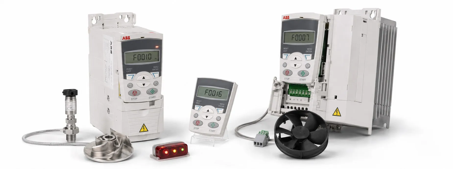
ABB ACS310 Fault Codes and Alarm Messages
Understanding alarms and faults
A fault on the ABB ACS310 is indicated by a red LED. An alarm or fault message on the control panel means the drive has detected an operating condition outside its normal limits.
The four-digit number shown in brackets with some messages is used for fieldbus communication and fault identification.
How to reset an ACS310 fault
The drive can be reset from the Basic or Assistant Control Panel, through a digital input, by fieldbus command, or by removing the supply voltage for a short time. The reset source is selected with 1604 FAULT RESET SEL.
Important: Do not keep resetting the drive without finding the reason for the trip. Overcurrent, overtemperature, phase-loss and motor-stall alarms usually need the motor, wiring or mechanical load checked first.
Fault history
When the ACS310 detects a fault, it stores the event in its fault history. The most recent records can be checked from:
0401 LAST FAULT
0412 PREVIOUS FAULT 1
0413 PREVIOUS FAULT 2
Parameters 0404...0409 show drive operating data from the time the latest fault occurred. If you are chasing an intermittent problem, these values are often more useful than the fault code alone.
2001 OVERCURRENT – 0308 bit 0
The output current limit controller is active.
Check the motor load, acceleration time and motor wiring. Relevant ramp parameters are 2202 and 2205. Also check motor phasing and the motor cable.
If the installation ambient temperature is above 40 °C, the available drive load capacity may be reduced.
2002 OVERVOLTAGE – 0308 bit 1
The DC overvoltage controller is active.
Check deceleration parameters 2203 and 2206. Also check the incoming supply for static or transient overvoltage.
2003 UNDERVOLTAGE – 0308 bit 2
The DC undervoltage controller is active. Check the input power supply and supply voltage.
2004 DIR LOCK – 0308 bit 3
A change of motor direction is not permitted. Check 1003 DIRECTION.
2005 IO COMM – 0308 bit 4
Fieldbus communication has been lost. Check the fieldbus connection, wiring and master device.
Also check programmable fault parameters 3018 and 3019.
2006 AI1 LOSS – 0308 bit 5
Analog input AI1 has fallen below the limit set by 3021 AI1 FAULT LIMIT.
Check the analog signal level, wiring and the related fault-function settings.
2007 AI2 LOSS – 0308 bit 6
Analog input AI2 has fallen below the limit set by 3022 AI2 FAULT LIMIT.
Check the signal level, analog wiring and parameters 3001 / 3022.
2008 PANEL LOSS – 0308 bit 7
The control panel selected as an active control location is no longer communicating with the drive.
Check the panel connection, connector and mounting platform. If the drive is in REM mode and accepts commands from the panel, also check Group 10 START/STOP/DIR and Group 11 REFERENCE SELECT.
2009 DEVICE OVERTEMP – 0308 bit 8
Drive IGBT temperature is too high. The alarm limit given in the source manual is 120 °C.
Check ambient conditions, airflow and the cooling fan. Also make sure the motor power and drive rating are suitable for each other.
2010 MOTOR TEMP – 0305 bit 9
Motor temperature is too high, or the drive calculates it as too high. Common causes are excessive load, inadequate cooling, incorrect start-up data or incorrect temperature-sensor settings.
Check motor ratings, load, cooling and start-up data.
If measured motor temperature is being used, check 3503 ALARM LIMIT and confirm that the installed temperature sensors match the setting in 3501 SENSOR TYPE.
2012 MOTOR STALL – 0308 bit 11
The motor is operating in the stall region, usually because of excessive mechanical load or insufficient motor power.
Check the machine, motor load, drive rating and parameters 3010...3012.
2013 AUTORESET – 0308 bit 12
Automatic reset is active. Check Group 31 AUTOMATIC RESET.
2014 AUTOCHANGE – 0308 bit 13
The PFC Autochange function is active. Check Group 81 PFC CONTROL.
2015 PFC I LOCK – 0308 bit 14
PFC interlocks are active. Depending on the Autochange configuration, the drive may be prevented from starting the speed-controlled motor or any motor in the PFC group.
Check Group 81 PFC CONTROL and the external interlock signals.
2018 PID SLEEP – 0309 bit 1
The PID sleep function has entered sleep mode. Check parameter groups 40 PROCESS PID SET 1 and 41 PROCESS PID SET 2.
2021 START ENABLE MISSING – 0309 bit 4
Start Enable 1 has not been received. Check 1608 START ENABLE 1, the digital input wiring and fieldbus settings.
2022 START ENABLE 2 MISSING – 0309 bit 5
Start Enable 2 has not been received. Check 1609 START ENABLE 2, digital input wiring and fieldbus settings.
2023 EMERGENCY STOP – 0309 bit 6
The drive has received an emergency-stop command and is stopping according to the ramp set by 2208 EMERG DEC TIME.
Before resetting it, make sure the machine is safe to restart and return the emergency-stop circuit to its normal condition.
2025 FIRST START – 0309 bit 8
Motor identification magnetization is active. This is a normal start-up message. Wait until the drive completes the identification process.
2026 INPUT PHASE LOSS – 0306 bit 5
The intermediate DC voltage is oscillating because an input phase may be missing or a supply fuse may have failed.
Check the input fuses, phase voltages and supply imbalance. The source manual states that the alarm is generated when DC voltage ripple exceeds 14% of nominal DC voltage.
2027 USER LOAD CURVE – 0309 bit 10
The condition defined by 3701 USER LOAD C MODE has remained active longer than half of the time defined by 3703 USER LOAD C TIME.
Check Group 37 USER LOAD CURVE.
2028 START DELAY – 0309 bit 11
Start delay is currently active. Check 2113 START DELAY.
2030 INLET LOW – 0309 bit 13
Pressure at the pump or fan inlet is too low.
Check for a closed inlet valve, leaking pipework or another restriction on the suction side. See Group 44 PUMP PROTECTION.
2031 OUTLET HIGH – 0309 bit 14
Pump or fan outlet pressure is too high. Check the discharge piping for blockage and review Group 44 PUMP PROTECTION.
2032 PIPE FILL – 0309 bit 15
The pipe-fill sequence is in progress. Check parameters 4421...4426.
2033 INLET VERY LOW – 0310 bit 0
Inlet pressure is very low. Check the inlet valve and pipework for leaks. See Group 44 PUMP PROTECTION.
2034 OUTLET VERY HIGH – 0310 bit 1
Outlet pressure is very high. Check the discharge pipe for blockage and review Group 44 PUMP PROTECTION.
Basic Control Panel messages
5001 – Drive is not responding. Check the panel connection.
5002 – Incompatible communication profile.
5010 – Corrupted panel parameter backup file. Retry the parameter upload or download.
5011 – The drive is controlled from another source. Switch the drive to local control.
5012 – Direction of rotation is locked. Check 1003 DIRECTION.
5013 – Panel control is disabled because Start Inhibit is active. Check the emergency-stop or 3-wire stop command and the related start-command settings.
5014 – Panel control is disabled because an active drive fault is present. Clear the fault and retry.
5015 – Local-control lock is active. Check 1606 LOCAL LOCK.
5018 – Parameter default value was not found.
5019 – Writing a non-zero parameter value is not allowed. Only parameter reset is permitted.
5020 – Parameter or parameter group does not exist, or the value is inconsistent.
5021 – Parameter or parameter group is hidden.
5022 – Parameter is write-protected and cannot be changed.
5023 – Parameter cannot be changed while the drive is running. Stop the drive and try again.
5024 – The drive is already carrying out another task. Wait until it finishes.
5025 – Software or data transfer is in progress. Wait until the operation is complete.
5026 – Value is at or below the minimum limit.
5027 – Value is at or above the maximum limit.
5028 – Invalid value.
5029 – Memory is not ready. Retry the operation.
5030 – Invalid request.
5031 – Drive is not ready for operation, for example because DC voltage is too low. Check the input supply.
5032 – Parameter error.
5040 – Parameter download error. The selected parameter set is not in the current backup file.
5041 – Parameter backup file does not fit into memory.
5042 – Selected parameter set is missing from the current backup file.
5043 – No start inhibit.
5044 – Parameter backup restore error. Check that the file is compatible with the drive.
5050 – Parameter upload was aborted. Retry the upload.
5051 – File error.
5052 – Parameter upload failed. Retry.
5060 – Parameter download was aborted. Retry the download.
5062 – Parameter download failed. Retry.
5070 – Panel backup-memory write error.
5071 – Panel backup-memory read error.
5080 – Operation is not allowed because the drive is not in local-control mode. Switch to local control.
5081 – Operation is blocked by an active fault. Find the cause, reset the fault and retry.
5083 – Parameter lock is active. Check 1602 PARAMETER LOCK.
5084 – The drive is performing another task. Wait until it is complete.
5085 – Parameter transfer from the source drive to the destination drive failed. Check that both drives are the same type, for example ACS310.
5086 – Source and destination drive type designations do not match. Check the drive labels.
5087 – Parameter sets are incompatible. Compare source and destination drive information in Group 33 INFORMATION.
5088 – Operation failed because of a drive memory error.
5089 – Download failed because of a CRC error.
5090 – Download failed because of a data-processing error.
5091 – Operation failed because of a parameter error.
5092 – Parameter transfer failed because the parameter sets are incompatible. Compare the source and destination drive data in Group 33 INFORMATION.
ACS310 manuals and technical support
With ACS310 faults, the code on the display is only the starting point. For overcurrent, motor-temperature, pump-protection or communication problems, it is worth checking the recorded operating values and the related parameter group before changing anything.
- ABB ACS310 user manuals and files
Support note: Basic commissioning and fault-code support is available for ABB products purchased through OtomasyonAVM. Contact details are available on our ABB page.